D3 Performance Engineering GT500 Project
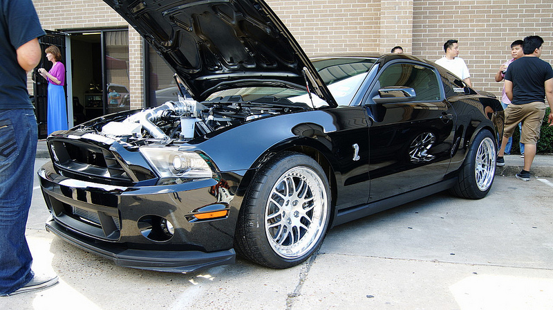
This 2010 Ford GT500 was brought to us by its owner Dai Nguyen, it already had the supercharger deleted and was running an off the shelf twin turbo kit, but he was displeased with the fact it ran the stock manifolds, placed the turbos under the engine close to the ground, and wouldn’t allow him to run a auto trans in the future. His request was he wanted a top notch turbo system that placed the Precision 6466 turbos up front, was capable of 1400whp if he wanted to go that high, had AC and power steering and the rest he left up to us.
The first thing we started with was the turbo manifolds, we chose 321 stainless for the material and double slip fit collectors to handle the high egts that we would see before the turbos. We solid mounted the engine, then made mounts for the turbo, then made the manifolds to them. We also added vibrant interlocking vbands between the collector and overpipes to allow removal of the overpipe to service the vehicle if needed. We also added 1/8NPT female bungs for the back pressure sensors we will be running. Everything was back purged while being welded with 347 tig rod.
The downpipes are 3.00″ and constructed from 16g 304L stainless, all with interlocking vbands. On the drivers side though, space was so tight that we had to transition from circle to oval then back to circle to clear the steering rod, using vibrant products for this. We also recirculated the Tial 44mm wastegates using 1.75″ 16g 304L with vibrant flex bellows back into the downpipes. Again everything was back purged while welding with 316 tig rod.
Once that was completed, the next step we did was fabricate a 3.00″ x-pipe to connect the downpipes to an off the shelf 3.00″ dual exhaust the customer already had. We used 304L 16g tubing for this along with vibrant interlocking vbands to connect it all, everything back purged.
Next we moved onto the aluminum side of the build. Since we will be running the OEM air to water intercooler built into the intake manifold along with a ProEFi engine management system, we opted to build our own IM tophat using a LS3 throttle body forward facing so we could use vibrant vanjen clamps. We started this process by reverse engineering the oem flange, then I moved over to designing it in solidworks. After we finalized the design we had it machined and started the sheet metal side of it. After gathering our measurements for it, we again went to solidworks and designed the sheet metal part. After we finalized it, we built it out of .125 5052 aluminum and welded it up inside and out, adding needed sensor bungs.
After that, we needed to fabricate the charge piping, which we constructed from a mixture of 4.00″ and 3.00″ aluminum mandrel bends, we finished them off by adding a 4.00″ vanjen assembly to the throttle body, 2.50″ vanjens to the turbos, 1/8npt bung for the nitrous, and two Tial Q50 blow off valve flanges.
Next we moved onto upgrading the factory components around the air to water system. We started by fabricating a large production heat exchanger, we started with a 3.25″ thick, 24.00″ wide, and 12.00″ tall usa made core. Then we designed and fabricated the tanks from .125 5052 aluminum to make the unit triple pass along with mounting brackets.
Next we knew we wanted to add more fluid volume to the heat exchanger system, so we designed and built a production trunk mounted fluid tank. We designed it in solidworks to hold 8.50 gallons of fluid. We constructed it from .125 5052 aluminum, adding 1.00″ NPT inlet and outlet fittings to be able to run large pumps, along with -10 AN drain fitting for running ice. We finished it off with mounting points using countersink fasteners for a nice clean look.
From there, we moved onto the cooling system. We removed the intake manifold and welded AN fittings for the upper coolant and bleed lines. We reinstalled it then began design and fabrication of the radiator. OEM flowed side to side, we needed to flow vertically. We speced out a thicker USA made core, then designed and built the tanks. We finished it off with AN fittings for the coolant hoses. Next we designed a coolant overflow/fill tank that would sit on top of the radiator. We designed it in solidworks then fabricated it out of .125 5052 aluminum with AN fittings and tubing fill outlet that fed the lower radiator/distribution hose we fabricated. We fastened this to the radiator using countersinks.
Next we designed and fabricated a production catch can system to deal with the added crankcase pressure from the high boost. We took some measurements and finalized a design in solidworks then fabricated it out of .125 5052 aluminum. We used cnc cut barbs and AN fittings throughout. It features 2 large filters and -12 AN hoses.
The final items we fabricated were small brackets for the regulator, factory pcm and ProEFI ecu which is mounted in the fender, boost controller, abs unit mount, fuse box mount to mount in bumper, water pump mount, nitrous solenoid mount, battery box mount, and racepak bezel/mount.
We are currently wrapping up the complete race wiring for the vehicle including ProEFI standalone, traction control, nitrous, racepak dash, proefi can display, and staged fuel pump control while we wait for the turbo components to come back from coating/ polishing. Once that is completed we will start tuning and hit the track.
Items Fabricated:
321 slip fit Turbo manifolds
V-band Downpipes with recirculated dumptubes
V-band x-pipe
Intake manifold top hat with ls3 throttle body
Charge piping with vanjen clamps
8.50 gallon production trunk mounted air to water tank
Large production heat exchanger
Production catch can system
Radiator with AN fittings
Coolant overflow/fill tank
Lower radiator/distribution hose
PCM/ProEFI ecu mount
nitrous solenoid mount
regulator mount
ABS motor mount
Fuse box mount
Water pump mount
battery box mount
RacePak dash panel/mount
Material Used:
321 stainless tubing
304 stainless tubing
6061 aluminum plate
5052 aluminum tubing and sheet
Equipment used:
Miller Syncrowave 300 tig welder
Miller Syncrowave 250 tig welder
Haas mill
Pexto stomp shear
Box pan brake
vertical band saw
horizontal band saw
6×48 sander
table top press brake
Build time:
1 month
HP Goal:
1200-1400whp
Vehicle Owner:
Dai Nguyen